
Products
Recommend Products
Contact Us
| Email: | info@sanchangpump.net |
| Hotline: | +86 181 4266 2779 |
| +86 193 1300 1794 | |
|
Wechat: |
+86 181 4266 2779 |
|
WhatsApp: |
+86 181 4266 2779 |
| Address: | No.517,Xiangfu Road |
| Yuhua District, | |
| Changsha City | |
| Hunan Province, P.R.C |

AY Type API 610 BB2 Chemical Process Centrifugal Pump
Classification:
API 610 Pump
Petrochemical Industry
Salt Chemical Industry
Key words:
Chemical Process Pump
Centrifugal Pump
BB2 Pump
Hotline:
- Product Description
- Performance Parameter
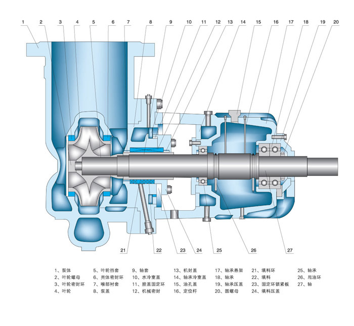
- Installation Drawings
- Installation And Use
- Faults And Solutions
-
- Commodity name: AY Type API 610 BB2 Chemical Process Centrifugal Pump
Flow Range: 2.5~800 m3/h</br> Head Range: 30~330 m</br> Fluid Temperature: -45~420 ℃</br></br></br></br></br></br></br>
Product Description
Our standard single-stage API 610 BB2 type pumps are center line-mounted, radially split, and feature a double-suction design with bearings located between the suction and discharge ends.
These pumps and their motors are flexibly coupled and mounted on a shared base plate.The radial casing pull-out design allows for the removal of the rotor assembly without the need to disturb the driver, coupling hubs, or casing nozzle connections

Product Profiles
- BB2 series heavy-duty chemical process pumps are horizontal, radially split, supported at both ends, and centerline mounted centrifugal pumps.
- They are designed to meet demanding working conditions and can be divided into single-stage, two-stage, and three-stage structures.
- They are highly efficient, energy-saving, highly reliable, high temperature resistant, and high pressure resistant.
- They are widely used in oil refining, petrochemicals, and other industries to transport high-temperature, high-pressure, or corrosive liquids.
Product Features
- Between bearings, centerline mounted, minimize displacement by heat expansion and cold contraction.
- Double volute, dynamically balanced, self-venting design.
- Top suction and top discharge, full access case cover for both ends.
- Shaft designed working in tensile stress preventing rotors play.
- API 682 seal chamber accommodates multiple seal types and pipe plan.
- Radially split casing with spacer coupling, replacement to impeller, seal or bearing without dismounting pump casing.
Applications
- High pressure application.
- Sour water.
- Propane.
- Light hydrocarbons.
- Hot and corrosive naphthenic crude oil.
- Hot sandy crude oil.
- Vacuum bottoms.
- Refining.
- Petrochemical.
- Gas processing.
- Synfuels.
- Offshore.
-
Flow Range: 2.5~800 m3/h
Head Range: 30~330 m
Fluid Temperature: -45~420 ℃
-
-
1. General Installation Requirements
1. Installation and alignment shall be carried out meticulously. Poor installation will seriously affect the pump's stable operation and service life.
2. The installation height, length and pipe diameter of the pump suction pipeline shall comply with calculated values. Keep the pipeline as short as possible to minimize pressure loss, and ensure the pump operates within the allowable net positive suction head (NPSH).
3. Supports shall be fitted for both suction and discharge pipelines. The pump shall not bear any load from connected pipelines.
4. The installation site shall be spacious enough to facilitate subsequent maintenance and inspection.
2. Installation Procedure
1. Place the pump unit on the foundation pre-embedded with anchor bolts. Use paired wedge shims between the base and foundation for level alignment.
2. Disconnect the coupling. Place level gauges on the pump shaft and base respectively. Adjust the wedge shims to level the unit, then lightly tighten the anchor bolts to prevent displacement.
3. Align the concentricity of the pump shaft and motor shaft. The allowable deviation of the coupling face clearance is 0.1 mm, and the total tolerance for uniform clearance is 0.3 mm.
4. After connecting all pipelines and confirming the motor rotation direction, refit the coupling and recheck the shaft concentricity.
5. Conduct a final inspection after 2 to 3 hours of trial operation. The installation is deemed qualified if no abnormalities occur. Monitor bearing temperature and vibration during the trial run.
6. Cover all openings of the unit during installation to prevent foreign matter from entering the equipment.
7. For newly installed pipelines, install a strainer on the suction side of the pump to block debris. The effective cross-sectional area of the strainer shall be 2 to 3 times that of the suction pipeline.
-
1. Pump fails to start or starts with excessive load
1. Pump fails to start or starts with excessive load
(1) Abnormal prime mover or power supply
Solution: Check the power supply and prime mover.
(2) Pump seized
Solution: Rotate the coupling manually for inspection. Dismantle the pump if necessary and eliminate faults of rotating and stationary parts.
(3) Over-tightened packing
Solution: Loosen the packing.
(4) Discharge valve not closed
Solution: Close the discharge valve and restart the pump.
(5) Blocked balance pipe
Solution: Clear the balance pipe.
2. No liquid discharged from the pump
(1) Insufficient priming (gas not fully exhausted inside the pump)
Solution: Re-prime the pump.
(2) Wrong rotation direction
Solution: Verify the rotation direction.
(3) Excessively low rotating speed
Solution: Check and increase the rotating speed.
(4) Clogged strainer or malfunctioning foot valve
Solution: Inspect the strainer and remove foreign debris.
(5) Excessive suction lift or vacuum inside the liquid suction tank
Solution: Reduce the suction lift; check the pressure of the suction tank.
3. Liquid discharge interrupted after normal operation
(1) Air leakage from the suction pipeline
Solution: Inspect pipe joints and packing gland seals on the suction side.
(2) Residual gas on the suction side after priming
Solution: Re-prime the pump thoroughly.
(3) Suction port suddenly blocked by foreign objects
Solution: Stop the pump and remove the obstructions.
(4) Large amount of gas drawn in
Solution: Check for vortex at the suction inlet and verify the liquid submergence depth.
4. Insufficient flow rate
(1) Same causes as Item 2 (b, c)
Solution: Adopt corresponding remedies.
(2) Increased static head of the system
Solution: Check liquid level and system pressure.
(3) Increased resistance loss
Solution: Inspect pipelines, check valves and other obstructions.
(4) Severe wear of wear rings on pump casing and impeller
Solution: Replace or repair the wear rings and impeller.
(5) Liquid leakage at other positions
Solution: Inspect shaft seals and related components.
(6) Clogging, wear or corrosion of pump impeller
Solution: Clean, inspect or replace the impeller.
5. Insufficient head
(1) Same causes as Item 2 (1)(2)(3)(4), Item 3 (1) and Item 4 (6)
Solution: Adopt corresponding remedies.
(2) Reversed installation of double-suction impeller
Solution: Inspect and reinstall the impeller correctly.
(3) Liquid density and viscosity inconsistent with design parameters
Solution: Test the physical properties of the liquid.
(4) Excessively high operating flow rate
Solution: Reduce the flow rate.
6. Excessive power consumption during operation
(1) Friction between impeller and wear ring, or between impeller and pump casing
Solution: Inspect and repair the faulty parts.
(2) Same cause as Item 5 (4)
Solution: Reduce the flow rate.
(3) Increased liquid density
Solution: Check the liquid density.
(4) Over-tightened packing or dry friction
Solution: Loosen the packing and inspect the sealing water pipe.
(5) Damaged bearing
Solution: Inspect, repair or replace the bearing.
(6) Excessively high rotating speed
Solution: Check the driver and power supply.
(7) Bent pump shaft
Solution: Straighten the pump shaft.
(8) Malfunction of axial thrust balancing device
Solution: Check whether balance holes and return pipes are blocked.
(9) Misaligned coupling or too small axial clearance
Solution: Check coupling alignment and adjust the axial clearance.
7. Pump vibration or abnormal noise
(1) Same causes as Item 3 (4), Item 6 (5)(7)(9)
Solution: Adopt corresponding remedies.
(2) Vibration frequency: 0~40% of rated speed
Causes: Excessive bearing clearance, loose bearing bush, impurities in lubricating oil, poor oil quality (viscosity & temperature), oil foaming caused by air or process liquid, poor lubrication, damaged bearings.
Solution: Take targeted measures after inspection, such as adjusting bearing clearance, removing impurities and replacing lubricating oil.
(3) Vibration frequency: 60%~100% of rated speed
Causes: Bearing faults as described in (2), excessive seal clearance, loose retaining ring or worn seal.
Solution: Inspect, adjust or replace the seal assembly.
(4) Vibration frequency: 2 times of rated speed
Causes: Misalignment, loose coupling, seal friction, deformed pump casing, damaged bearings, support resonance, damaged thrust bearing, bent shaft and poor fitting tolerance.
Solution: Inspect, repair, adjust or replace relevant components.
(5) Vibration frequency: n times of rated speed
Causes: Pressure pulsation, misalignment, deformed casing, seal friction, base/support resonance, pipeline or unit resonance.
Solution: Follow remedies in (4); reinforce the foundation or pipelines.
(6) Extremely high vibration frequency
Causes: Shaft friction, inaccurate sealing and bearings, bearing chattering and defective shrink fit.
Solution: Follow remedies in (4).
8. Overheated bearing
(1) Substandard scraping and fitting of bearing pads
Solution: Refurbish or replace the bearing pads.
(2) Insufficient bearing clearance
Solution: Readjust or re-scrape the bearing clearance.
(3) Insufficient or deteriorated lubricating oil
Solution: Top up lubricant or replace the oil.
(4) Improper bearing assembly
Solution: Recheck assembly and eliminate defects.
(5) Cooling water interruption
Solution: Inspect and repair the cooling system.
(6) Worn or loose bearing
Solution: Repair or replace the bearing; retighten relevant bolts if loose.
(7) Bent pump shaft
Solution: Straighten the pump shaft.
(8) Deformed oil slinger failing to rotate and deliver oil
Solution: Replace the oil slinger.
(9) Misaligned coupling or too small axial clearance
Solution: Check coupling alignment and adjust the axial clearance.
9. Overheated shaft seal
(1) Over-tightened packing or abnormal friction
Solution: Loosen the packing and inspect the sealing water pipe.
(2) Misaligned sealing ring and sealing water pipe
Solution: Realign the components.
(3) Malfunction of flushing and cooling system
Solution: Inspect the flushing and cooling circulation pipeline.
(4) Faulty mechanical seal
Solution: Inspect and repair the mechanical seal.
10. Excessive rotor axial movement
(1) Improper operation, operating condition far away from the design point
Solution: Standardize operation and keep the pump running near design conditions.
(2) Blocked balance pipeline
Solution: Clear the balance pipe.
(3) Unqualified material of balance disc and balance disc seat
Solution: Replace with balance disc and seat made of qualified materials.
11. Water hammer
(1) Sudden power failure causes system pressure fluctuation and negative pressure in discharge pipeline. Dissolved gas escapes and accumulates inside the pump and pipes.
Solution: Fully exhaust all gas from the system.
(2) Rapid backflow of high-pressure liquid column due to power failure, impacting the check valve plate at pump outlet.
Solution: Modify the layout of discharge pipelines and pipe fittings.
(3) Outlet valve closed too quickly
Solution: Close the valve slowly.
Previous Page
Next Page
Customer Case
Product Consulting
If you are interested in our products, please leave your email, we will contact you as soon as possible, thank you!


Hunan Sanchang Pump Co., Ltd.
| Email: | info@sanchangpump.net |
| Hotline: | +86 181 4266 2779 |
| +86 193 1300 1794 | |
| Mobile/Wechat/WhatsApp: | +86 181 4266 2779 |
| Address: | No.517,Xiangfu Road, Yuhua |
| District, Changsha City | |
| Hunan Province, P.R.C |
